Do It Yourself, 3D printer Style
What is the cheapest possible, real working 3D printer I can make without making compromises in terms of quality?
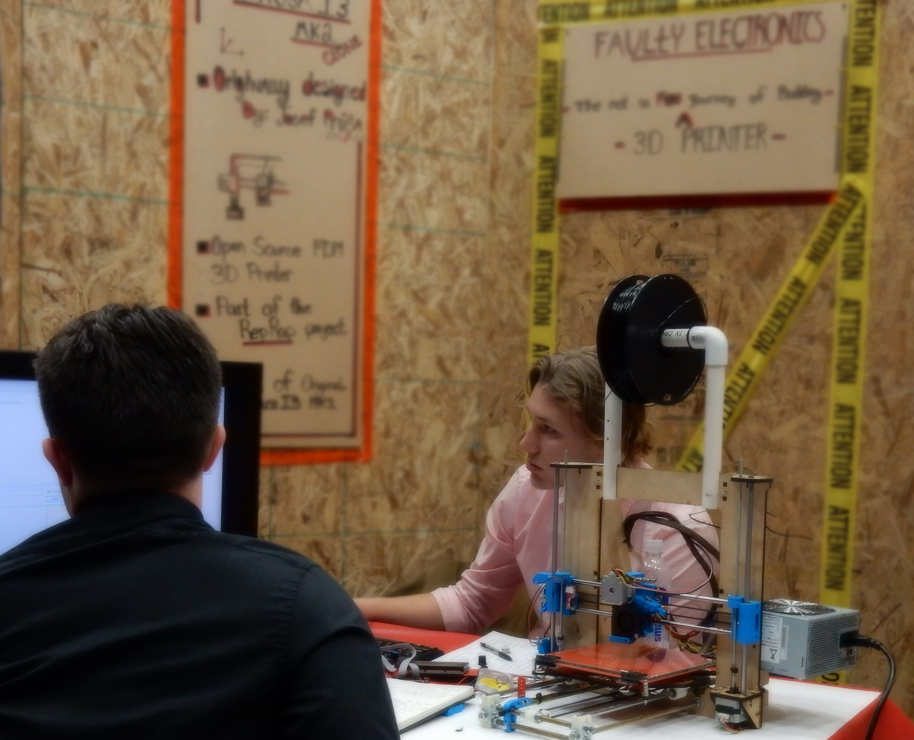
Each year the Ministry of Education allots our school district several scholarships worth $1250.00, based on the number of students enrolled in grade 12. Winners receive a Scholarship voucher, which may be used to attend a college or other post-secondary school. In-School District No. 22 (Vernon), candidates entering the District Scholarships must plan and complete a project to demonstrate a particular skill or interest outside of the regular school curriculum.
Problem:
My goal was to determine, "What is the cheapest possible, real working 3D printer I can make without making compromises in terms of quality?" With this challenge in mind I attempted to answer the question by building a Prusa i3 MK2-style clone that includes many of the major features of the original Josef Prusa model.
Design:The Prusia MK2 is the go-to design for most DIY 3D printers because of the sheer amount of open-source material on the design. The design includes many important features that are now a benchmark for current consumer 3D printers. The main difference between my printer and the original Prusia is the controller board. My clone is controlled by an Arduino Mega with a RAMPS 1.4 stepper motor driver shield, whereas the original is controlled by a RAMBO board.
My main goal with the project was to maintain quality while keeping the price of the project as low as possible. To achieve this goal I had to sacrifice in some areas and the area I sacrificed most was print speed. Using an Arduino to power a 3D printer has its drawbacks despite the low price, the main disadvantage is the 8bit processor, whereas compared to the 16bit processor of the RAMBO board the Arduino causes significant bottlenecking of the print speed around any circular extruder pathing.
Sacrifices also had to be made in build quality. compared to the original Prusias 3mm aluminum frame my clone is built with laser cut 1/4" MDF board. I choose MDF as the material for my structural frame because of the fiberboards natural tendency to absorb small vibrations and not warp with atmospheric moisture, and because MDF is very easy to laser-cut precisely.
The main structure apart from the frame was printed from another 3D printer. These parts were then connected using 3/8" threaded rod for the main structure these rods cause a lot of problems with alignment because they are usually bent slightly. The extruder movement was made using 8mm drill rod for the linear X & Y axis movement, and the first iteration used 1/4" threaded rods for Z axis movement which was instead later changed to lead screws.
Build process: The FrameThe building process started first by building the structural frame of the printer, the reason for this was Aliexpreses unusually long shipping times leaving enough time to build the structure and still take a nap. The frame was laser cut from 1/4" MDF by a friend at the local maker space club. The rest of the structure that holds the print bed and the Y-axis motion was built using threaded rod and 3d printed fasteners.
Print Bed Structure
Laser Cut Frame
Combined Printer Frame
Electronics and Linear Motion
The electrical portion of the project was based around the arduino mega and a RAMPS 1.4 shell.
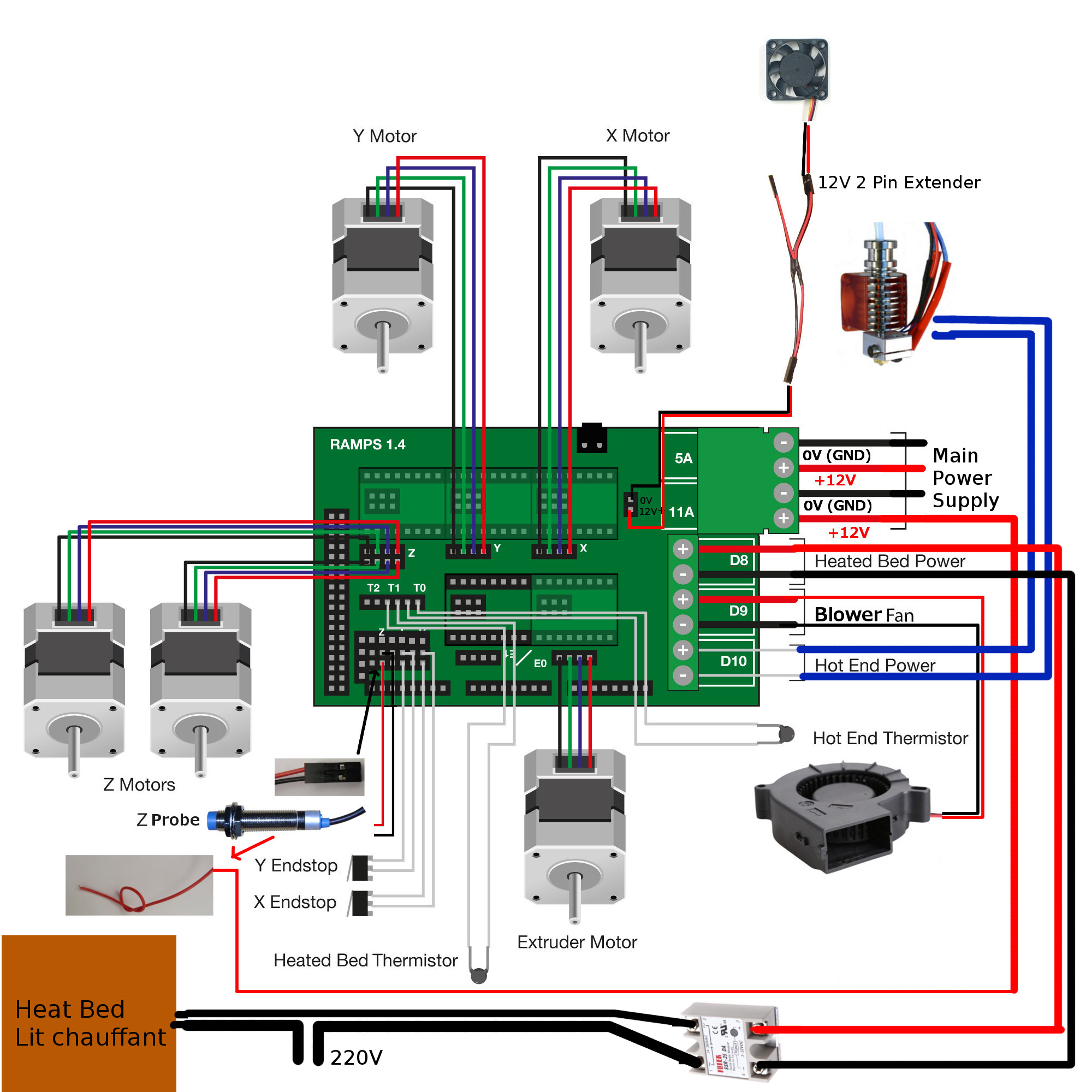
RAMPS Wiring Schematic
the basic wiring schematic for the prusia i3 MK2 clone controlled by a RAMPS shell: The major advantage of using this system is the simplicity of the design helping to mediate the cost of the project. Although, the disadvantage of this was how it made my printer lack many of the bells and whistles saw on many modern printers like multifilament extrusion, but I was still able to include many other important features such as print bed auto-leveling using an induction probe.
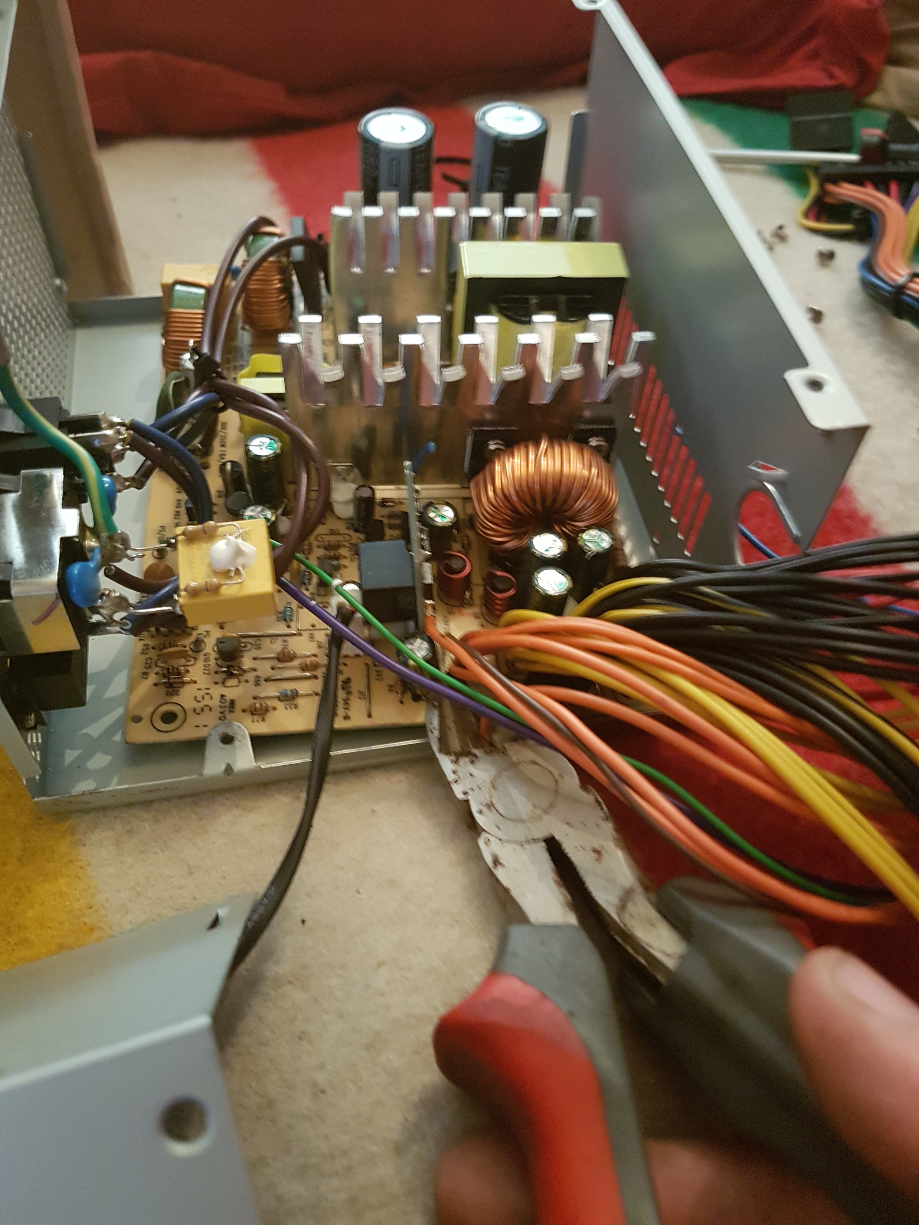
Modifying PSU
The power supply used for my project was a recycled computer ATX power supply which has 350 Watts of power output. The Reason for using the computer PSU instead of the more simplistic LED strip PSU was the price, a local computer store donated me this old PSU for the project, despite the low price tag it had an additional cost of time invested to modify things within the power supply for it to be able to provide reliable output.
The process of building the electronics for this project was very time consuming because it was the first time I ever did a project of this nature, This resulted in myself having to constantly troubleshoot problems with my design by consulting google other available resources.
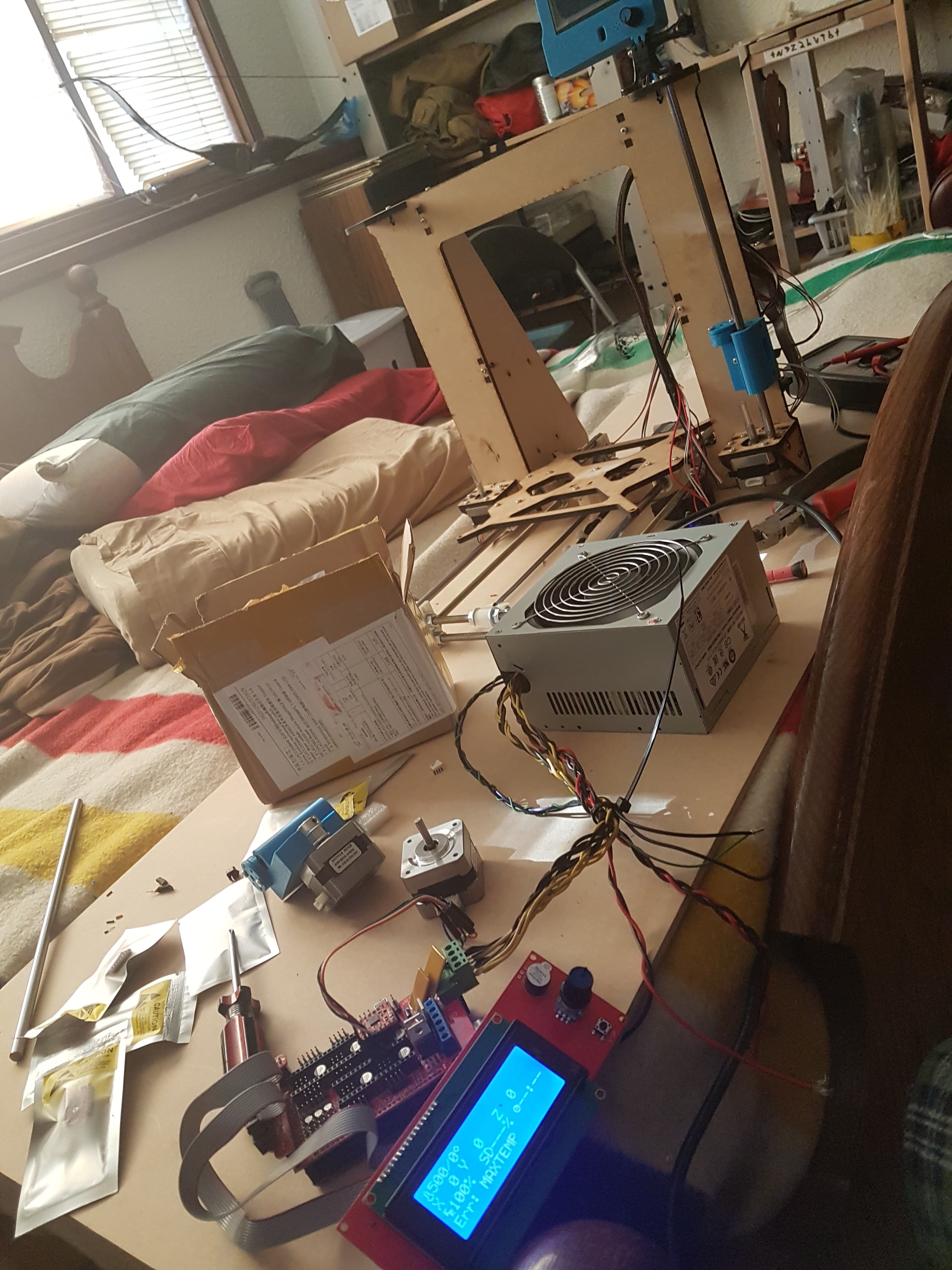
Testing Power Supply
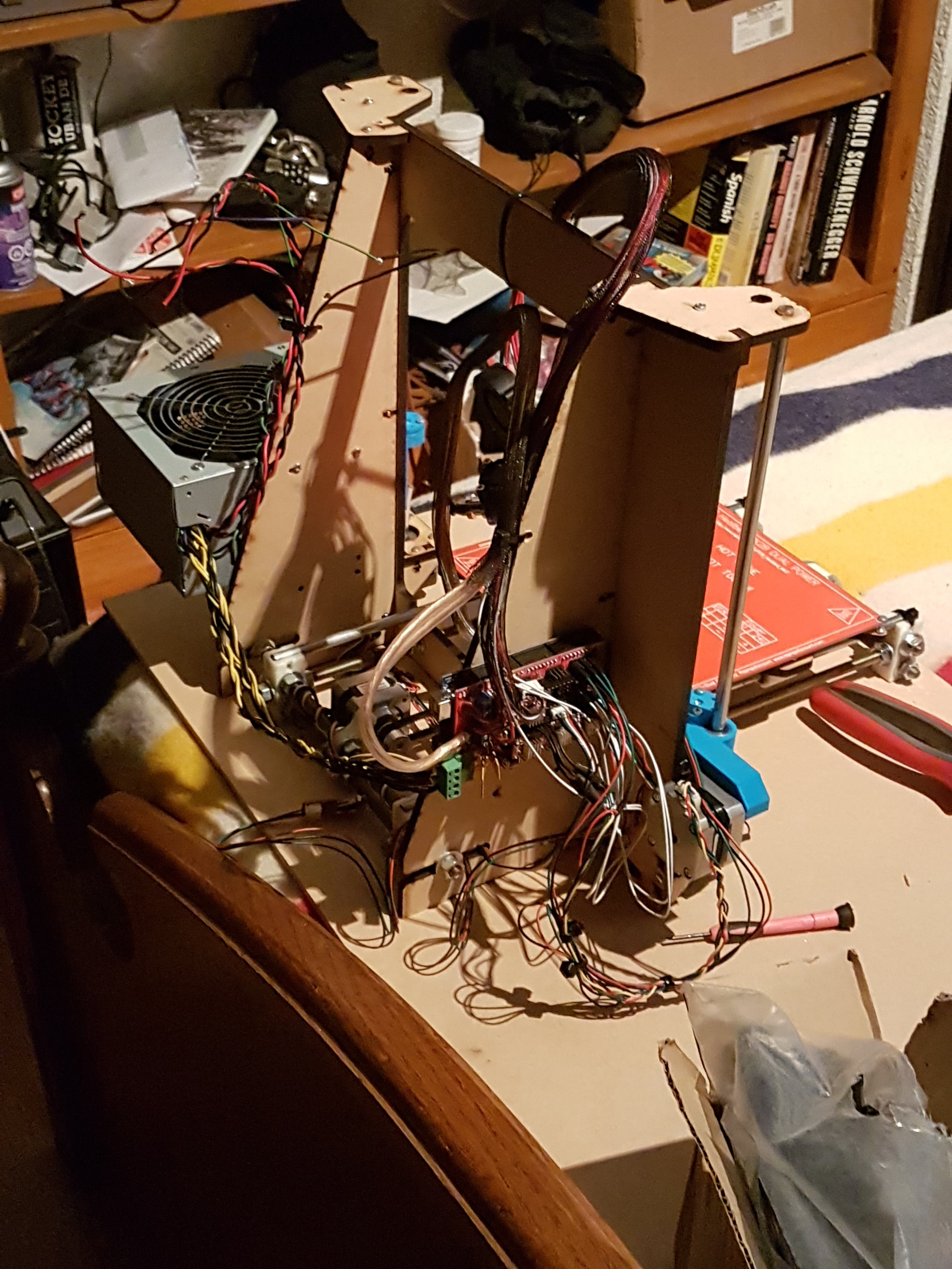
Wiring Process
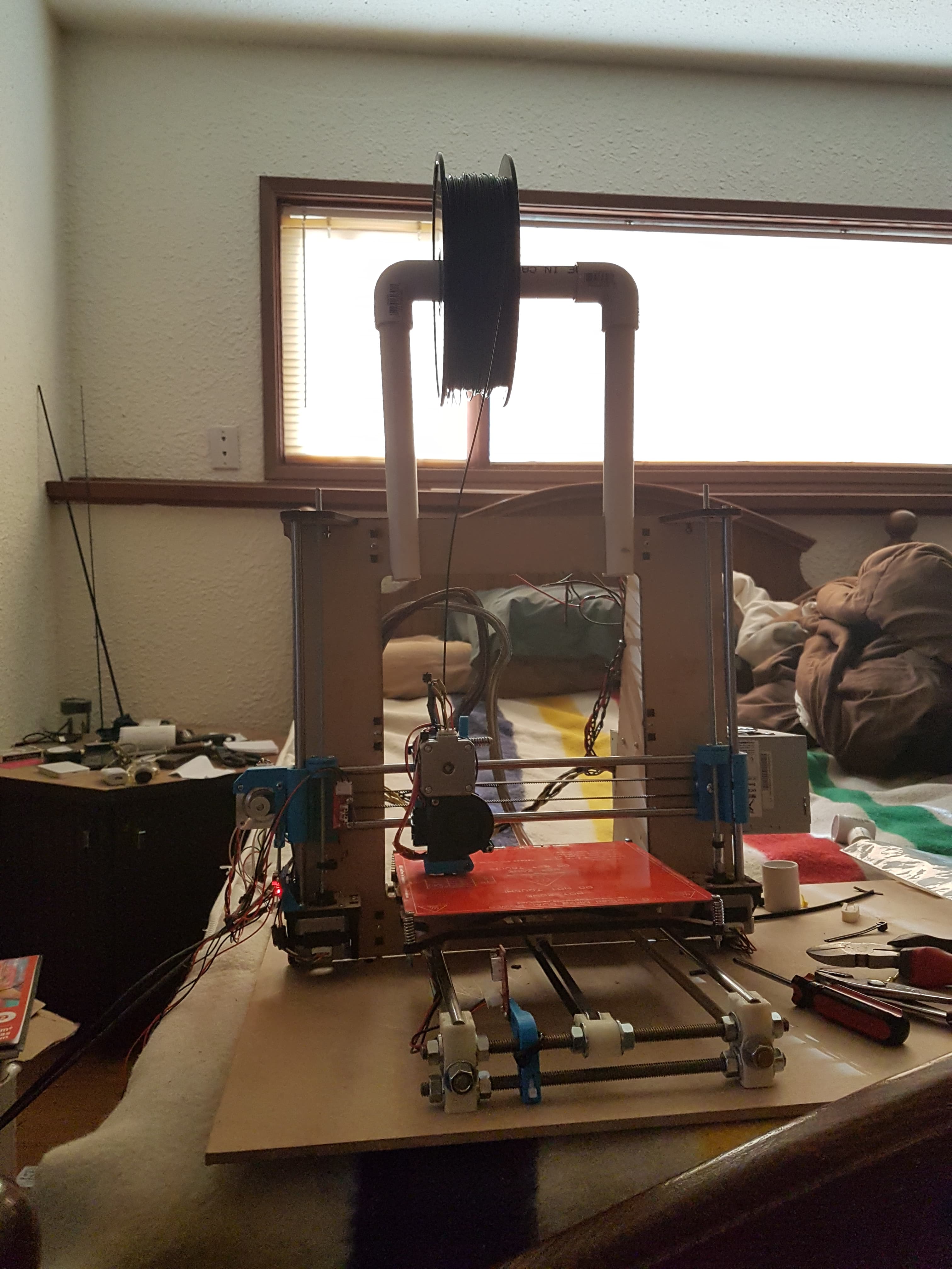
Completed Printer
The Big Picture: What I Learned
This project was something I wanted to do for many years before I decided to pursue it. The idea I could complete one of the projects I have thought about building while simultaneously helping fund my post-secondary was a very appealing position which I took full advantage. This project taught me so much about the basics of 3D printing, robotics, and most importantly how to troubleshoot issues I encounter throughout the building process. The main goal of the project was to keep the price of the printer as low as possible, which I was able to do relatively successfully, the total price for the project was under 300$ CAN, which is less than the average price of a mid-quality Chinese Clone.
Achievements- Most hours spent on one issue: 43.
- Best workspace: Workbench made with a sheet of plywood across my bed.
- Destroyed sleep cycle: What am I kidding that was wrecked way before this project.
- Recieved scholarship: I mean at least I got it.