Designing An E-sk8: Trying To Look Cool.
building and designing a electric skateboard with specification and reliability satisfactory for commuting purposes.
Context:
Current market electric skateboards are unreasonably priced if the customer wants quality. enjoying the idea of esk8s for commuting and generally wanting one I decided to design and buid one DIY style since i didnt have the money to buy one.
Key Skills:- Cirucit Design
- Prototyping
- Lithium Ion Cells
- Soldering
- Trouble-shooting
- Water Phobia
- RC design
- Variable tuning
- Get it working
The main goal for this project was building and designing an electric skateboard with the ability and reliability to commuting daily.
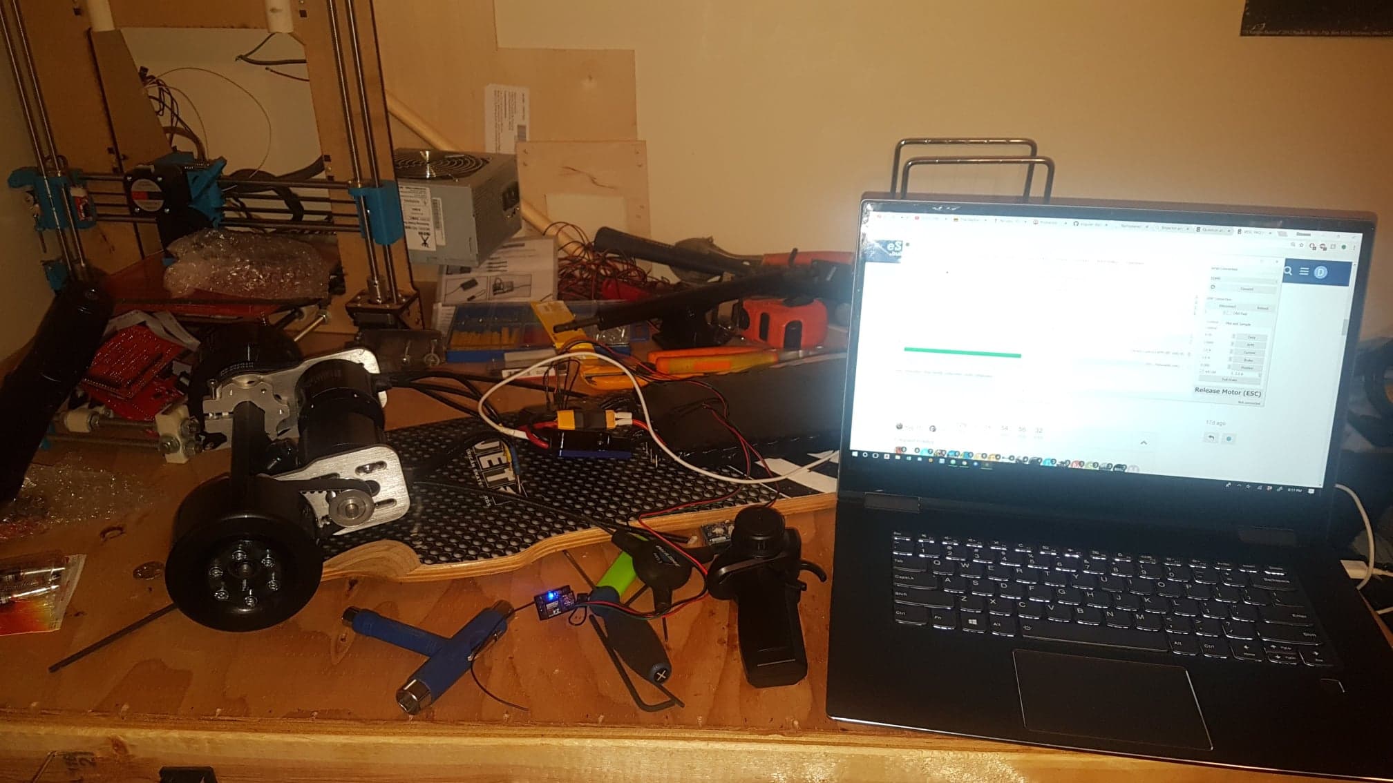
This page is a work in progress and doesnt have very much information on this project yet. It will be updated soon with build pictures and better discussion.
ResearchBefore jumping into designing or purchasing components, the first major undertaking for the project was research, and approaching the problem by first learning about solutions then applying that to form a design, then working prototype.
DIY electric skateboards have a thriving online community which I abused during the researching phase, by reading through countless build threads and other related posts. I used the build threads as a template for my project. I learned from other peoples experiences during their projects to better understand how to approach this project succesfully. This inspiration from other builds was very important for me while learning how to complete this project.
Hype:Researching made me super stoked, my mind was whirling with the idea of shredding. * In reality probably crashing *
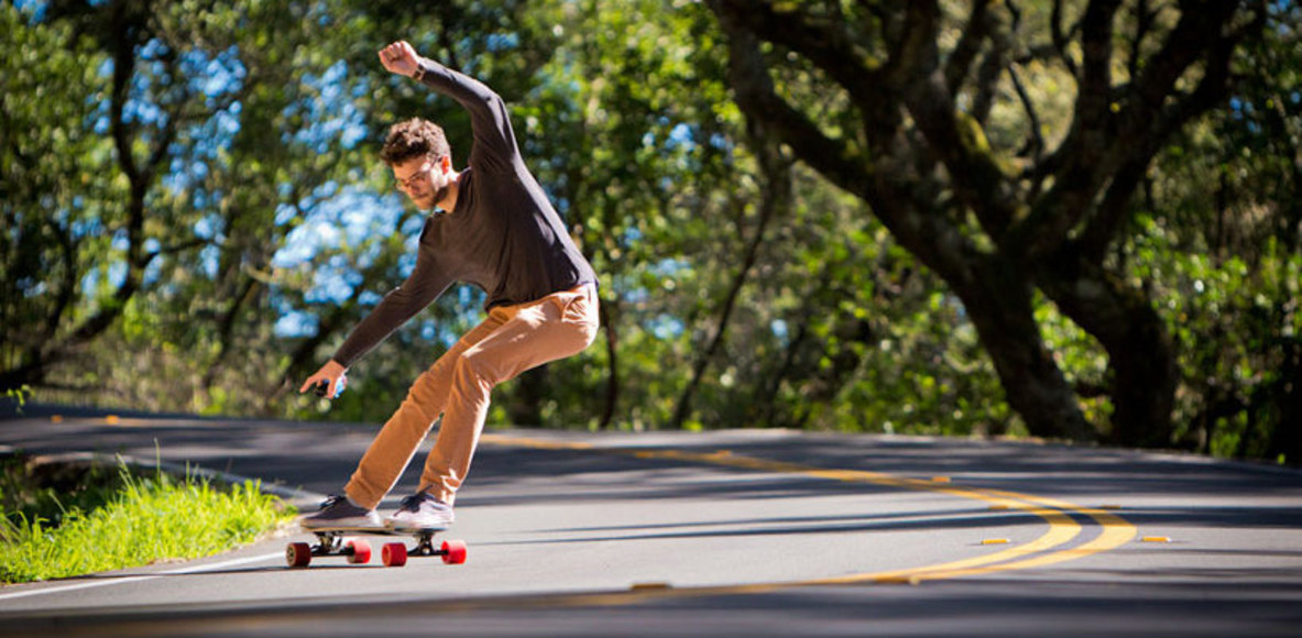 The Dream.
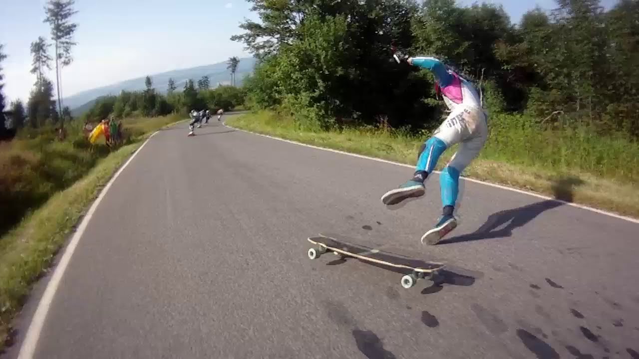 Reality.
Design:
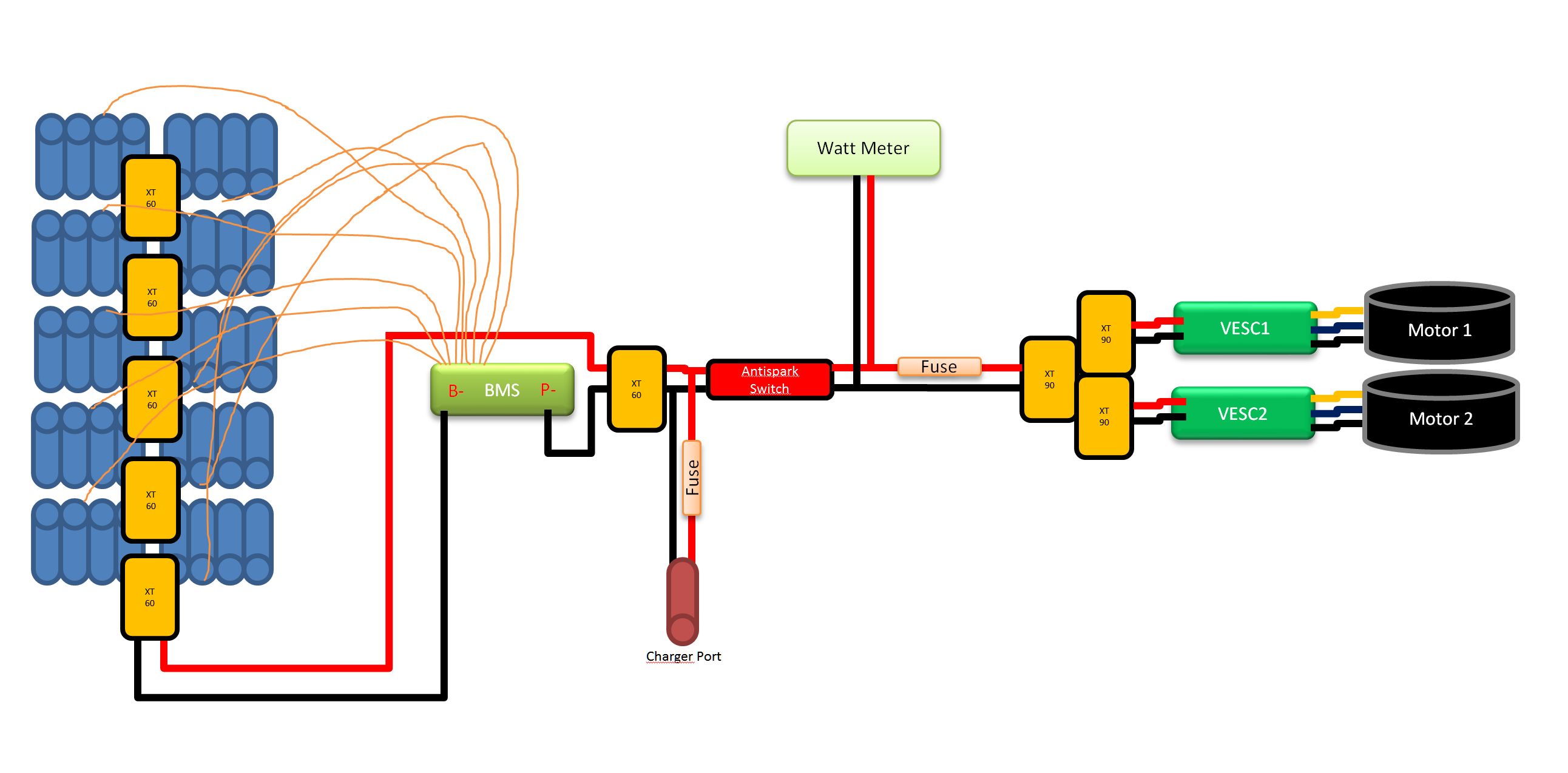 The wiring is illustrated by the above wiring schematic.
The board is powered by two 6374 160kv sensored prop motors made for an RC plane, these with the larger size will help prevent overheating when carrying load. both motors are controlled by a specailized esk8 motor controller deisnged to handle load when large amounts of current are pulled going up hills or accelerating, these motor controllers are an open source curcuit board designed by Veddar.
The battery is a 10s4p Li-ion pack, the cells are Samsung 30Q which are 3000 mAh each, therefore 12 Ah in a 4P configuration. This setup was calculated to last roughly 20-30km depending on speed and terrain, which is my goal travel distance. The pack was built in my shop using cell level fusing similar to what tesla batteries use, I used .032" brass for the bus with 26ga bus wires between each cell and the brass.
The battery pack is charged by a battery management system. This is to help prevent an electrical fire, and to monitor the cells condition to determine if any cells are at risk. The BMS is not used for output as it is only rated for 60 amp extended pull which could cause issues during extended hill climbs. The BMS might also cause problems by overcharging while braking down hills. The regenerative braking would cause the battery to over charge and the BMS in this situation would shutdown shutting down the moto controller making you lose brakes, which despite more fun is a non ideal situation.
Build process
The building process started with the chassis. I built this with the intention to keep the whole system water proof for better reliability. The first way to improve water resisitance was by sinking the wires within columns run the length of the board, by epoxying the wires into the deck like this it was able to avoid having to drill holes into the abs electronic enclosure.
The electronics which was designed around the large amount of continuous current required to move a human. Electronics were explained above
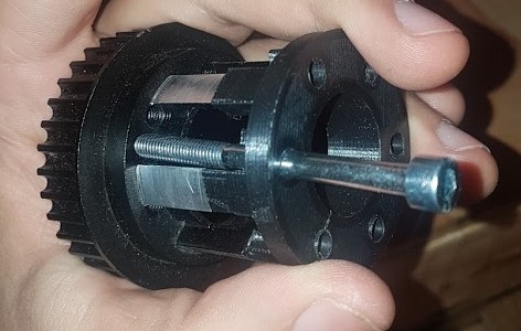
The drive train is made out of timing pulleys driven by the motors mounted on the skateboard trucks. The brackets holding the motors are milled out of aluminum and clamp to the truck. They allow adjustment of the motor position to correct belt tension and they have a machine screw locking the position at the desired point. This system helps limit slip.
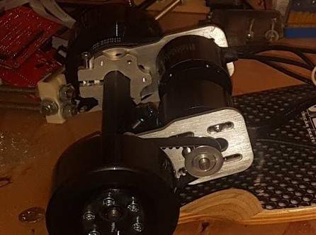
Gear ratio, without going into to much detail was determined by looking at the desired performance then building the system to achieve that result. The gear ratio was determined by both timing belt pulley but also by the size of the wheels. The wheels also effect high speed vibrations, speed wobble and handling. I settled on a larger wheel size to have a more comfortable ride the gear ratio was then calculated to be able to accelerate the larger wheels while staying in the ideal range of the motors curve.
The Big Picture:
This project was original started because I wanted an Esk8 but lead into something that allowed me to learn a lot of things about circuit design, high current systems and hardware among other things. I will soon revisit this project to rebuild the work I did in 2017 and produce a better product for myself to enjoy.
Achievements
- Largest spark: Wire cutters are better on one wire then two.
- Biggest crash: High speed wobble lead to fun looking road rash.
- Reliability: Has worked reliably since completion
- Fastest speed: Fastest speed achieved is 37km/h.